

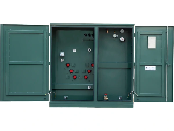
Planning a transformer room requires more than finding an empty corner of a building. The room must accommodate the transformer, provide enough space for safe operation, allow heat to escape, and give electrical technicians room to inspect and maintain the equipment. Poor planning can lead to installation delays, ventilation problems, difficult maintenance, and expensive changes during construction.
Understanding 30 kva transformer dimensions is a practical starting point for designing a suitable electrical room. However, the physical size of a 30 kVA transformer varies according to its construction, voltage ratings, cooling method, and manufacturer. Building plans should therefore use the selected unit’s technical drawings rather than a generic size estimate.
Start With the Actual Transformer Measurements
A 30 kVA transformer is commonly used in small commercial buildings, workshops, control systems, and other installations with moderate electrical demand. Its relatively modest capacity does not mean that every model will fit into the same space.
Dry-type transformers may have different dimensions from oil-filled models because their insulation and cooling arrangements differ. Single-phase and three-phase designs can also vary in width, height, and depth. Additional components, such as an enclosure, cable boxes, terminals, or protective accessories, may increase the overall footprint.
Before finalising the room layout, obtain the manufacturer’s dimensional drawing and technical data sheet. Confirm the following measurements:
- Overall width: The maximum horizontal measurement across the transformer or enclosure.
- Overall depth: The distance from the front to the rear, including protruding components.
- Overall height: The full height, including terminals, lifting fittings, and other projections where applicable.
- Weight: The total installed weight, including any required accessories or insulating liquid.
- Cable entry locations: The positions and sizes of incoming and outgoing cable connections.
- Service access requirements: The manufacturer’s recommended clearances for inspection, connections, and maintenance.
These measurements establish the equipment’s actual footprint. The room must then be designed around the clearances, access routes, and safety requirements specified for the installation.
Allow Space Beyond the Transformer Footprint
The transformer itself occupies only part of the room. Electrical installations also require space for cables, switchgear, protective equipment, ventilation openings, and maintenance activities.
For example, a transformer measuring 600 mm wide and 500 mm deep would have a footprint of 0.30 square metres. This figure describes only the area occupied by the equipment; it does not represent the minimum room size. Additional space may be required on several sides, depending on the design and applicable electrical regulations.
Avoid setting room dimensions by adding an arbitrary margin to the transformer measurements. The required clearance depends on the manufacturer’s instructions, terminal arrangement, voltage level, enclosure design, and local code.
The layout should allow technicians to reach inspection points and connections without removing unrelated equipment. Doors must open safely, and the transformer should not block access to distribution panels, emergency exits, or other essential building services.
If switchgear shares the room, include its operating and maintenance clearances in the initial drawing. Placing every component as close together as possible may save floor area on paper but create practical problems during commissioning and future repairs.
Plan Cable Routes Before Construction
Cable entry and exit arrangements can influence the room layout as much as the transformer dimensions. Incoming supply cables must connect to the appropriate terminals, while outgoing conductors carry power to distribution boards or downstream equipment.
The design should identify whether cables will enter through the floor, walls, or overhead cable trays. Underground routes may require trenches, ducts, or floor openings. Overhead routes need suitable supports, bending space, and access for cable installation.
Cable bending radius must follow the cable manufacturer’s specifications. A cable that cannot turn within its permitted radius may require a revised entry point or a larger service area.
Consider the location of termination boxes and the space needed to install cable lugs, tighten connections, and conduct electrical testing. Keep power cables arranged according to the approved design, with suitable separation from unrelated services where required.
Cable routes should also avoid creating trip hazards or obstructing maintenance access. Finalising these details before walls and floors are completed can prevent drilling, cutting, and other costly modifications later.
Provide Suitable Ventilation and Heat Removal
Transformers generate heat because of electrical losses in their cores and windings. If the room cannot dissipate that heat effectively, operating temperatures may rise beyond the equipment’s permitted limits.
Ventilation requirements depend on the transformer’s losses, cooling system, ambient temperature, room volume, and installation conditions. A dry-type transformer may rely on natural or forced air circulation, while an oil-filled unit transfers heat through its insulating liquid and external cooling surfaces.
The room design should provide the airflow specified by the manufacturer. Ventilation openings must not be blocked by stored materials, nearby walls, or later building modifications.
For enclosed installations, engineers may need to calculate the heat load and determine whether natural ventilation is sufficient or mechanical ventilation is required. The calculation should account for transformer losses and heat generated by other equipment in the room.
Air openings must also comply with fire protection, weatherproofing, security, and electrical safety requirements. In dusty or humid environments, suitable filtration or protective measures may be necessary, provided they do not restrict the required airflow.
Check the Floor, Foundation, and Access Route
A transformer room must support the equipment safely throughout its operating life. The floor or foundation should be designed for the transformer’s total weight and the loads imposed by its mounting arrangement.
The manufacturer’s drawings can provide equipment weight, mounting points, base dimensions, and anchoring details. A structural engineer should assess the supporting floor where required, particularly in upper-floor installations or buildings with limited load-bearing capacity.
Floor openings, cable trenches, and raised plinths should be coordinated with structural drawings. The finished surface must not interfere with equipment stability, drainage provisions, or access requirements.
Delivery planning also deserves attention. Measure door openings, corridor widths, turning areas, lift dimensions, and loading access before selecting the final equipment location. A transformer may fit comfortably inside the room but still be impossible to move through the building without special handling arrangements.
Include enough space for approved lifting equipment and safe positioning during installation. The manufacturer or qualified installer should confirm the handling method before delivery.
Follow Electrical Safety and Fire Requirements
Transformer rooms contain electrical equipment that can expose personnel to dangerous voltages and fault conditions. Their design must comply with applicable electrical regulations, building codes, utility requirements, and manufacturer instructions.
Clearances around live parts, switchgear, and the transformer must be appropriate for the installation. Earthing and bonding arrangements should be included in the electrical design, along with suitable overcurrent protection and other required protective devices.
Fire precautions depend on the transformer type, location, building use, and applicable rules. Oil-filled transformers may require specific provisions for insulating liquid, fire separation, or spill management. Dry-type units avoid some oil-related concerns but still produce heat and may have fire-safety requirements associated with their insulation materials.
Doors, access control, warning signs, and emergency arrangements should be designed for the room’s intended use. Avoid using the transformer room for general storage, since stored materials can obstruct access, restrict ventilation, and increase fire risks.
The final arrangement should be reviewed by a qualified electrical engineer before installation and energisation.
Consider Noise and Nearby Occupied Areas
Transformers can produce a continuous humming sound caused by magnetic forces in their cores and windings. The perceived noise depends on transformer design, loading, mounting, and the surrounding building structure.
A room located beside offices, meeting rooms, bedrooms, or healthcare spaces may require additional acoustic consideration. Structural vibration can travel through floors and walls, so the problem is not always solved by adding sound-absorbing material.
Review the manufacturer’s noise data and consider the proposed installation location early. Approved vibration-isolation measures may help where appropriate, but they must not compromise grounding, stability, cooling, or the manufacturer’s mounting requirements.
Ventilation openings and doors can also affect sound transmission. Any acoustic treatment should preserve the airflow and access required for safe transformer operation.
Prepare a Practical Transformer Room Layout
Before construction begins, prepare a scaled drawing that shows the transformer, switchgear, cable routes, doors, ventilation openings, and maintenance clearances. Include dimensions from the manufacturer’s documentation and identify the location of each major connection.
The drawing should also show the equipment’s delivery route and any space required for installation or replacement. Review the plan with the electrical contractor, structural engineer, architect, and building services team to identify conflicts before they reach the construction stage.
A final inspection of the completed room should verify clearances, ventilation, access, earthing, cable installation, and compliance with the approved design. Testing and commissioning must be carried out by qualified personnel before the equipment enters service.
Planning around 30 kva transformer dimensions works best when measurements are treated as the starting point rather than the complete design. A properly sized room accommodates the transformer and its supporting systems while allowing safe access, effective cooling, and straightforward maintenance. Using manufacturer drawings and professional engineering advice helps create an installation that fits the building without compromising electrical safety or long-term reliability.
